6-2-70 TRIPLEXER.
The following project has been submitted by Pat M1BNH, a previous club member.
THE 6-2-70 TRIPLEXER
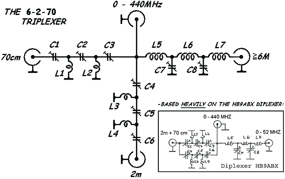
Based heavily on the HB9ABX Diplexer Article, plagiarised by Pat. Walton M1BNH
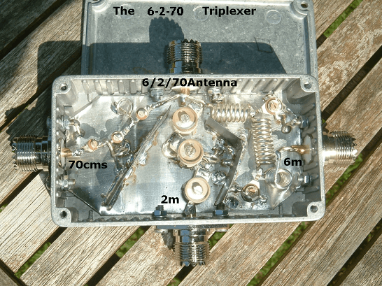
The TRIPLEXER below separates the following bands input to the top port:
- HF to 6m on the right-hand port (0 – 52MHz).
- 2m on the bottom port
- 70cm on the left port
It allows the simultaneous operation of 3 different equipments (HF, VHF & UHF) over one coax cable, or the use of 3 antennas for the corresponding bands with one coax cable.
The following data were measured at the 50Ω ports of the HB9ABX DIPLEXER:
– Attenuation of the other band is very high (over 60db)
– Insertion loss is negligible (less than 0.2db)
The circuit may be built easily into a solderable metallic box measuring about 11 x 5,5 x 3cm.
Here’s the circuit diagram of the Triplexer:
Adjustment procedure using a SWR meter:
1. Connect a 50Ω dummy load to the 0-440 MHZ socket on the triplexer. Fit suitable 50Ω terminations to all unused sockets.
2. Connect a SWR meter between the 0-52MHz socket on the triplexer and the 6m TRx and transmit a 51MHz carrier at low power. Adjust C7 and C8 to obtain 1:1 SWR. Then, with the SWR meter still set to ‘REVERSE’, turn the meter sensitivity to maximum and transmit and trim C7 and C8 again. NOTE C7 and C8 should reach the same value.
3. Connect a SWR meter between the 2m socket on the triplexer and the 2m TRx and Transmit a 145MHz carrier at low power. Adjust C4, C5, and C6 to obtain 1:1 SWR. Then, with the SWR meter still set to ‘REVERSE’, turn the meter sensitivity to maximum and transmit and trim C4, C5, and C6 again. NOTE C4 and C6 should reach the same value.
4. Connect a SWR meter between the 70cm socket on the triplexer and 70cm TRX and Transmit a 435MHz carrier at low power. Adjust C1, C2, and C3 to obtain 1:1 SWR. Then, with the SWR meter still set to ‘REVERSE’, turn the meter sensitivity to maximum and transmit and trim C1, C2, and C3 again. NOTE C1 and C3 should reach the same value.
5. Repeat steps 2 to 4 as necessary, as adjustment of one band influences the others. You will need some patience to reach proper adjustment on all bands.
Now the triplexer is ready for use. If an antenna analyser or VNA is available, use this instead of the SWR/ TX combination to make adjustment easier. Connect the analyser/VNA to plug 0 – 440 MHZ and dummy load to the plug being adjusted.
Note:
Foil capacitors can fail even at low power. Ceramic types (below) are stronger, good air trimmers are best.
As of 05/08/2020 this triplexer is now in use at M1BNH, connecting discrete UHF, VHF and 6m transceivers to a Diamond V-2000 antenna at a maximum RF power output of 25w.